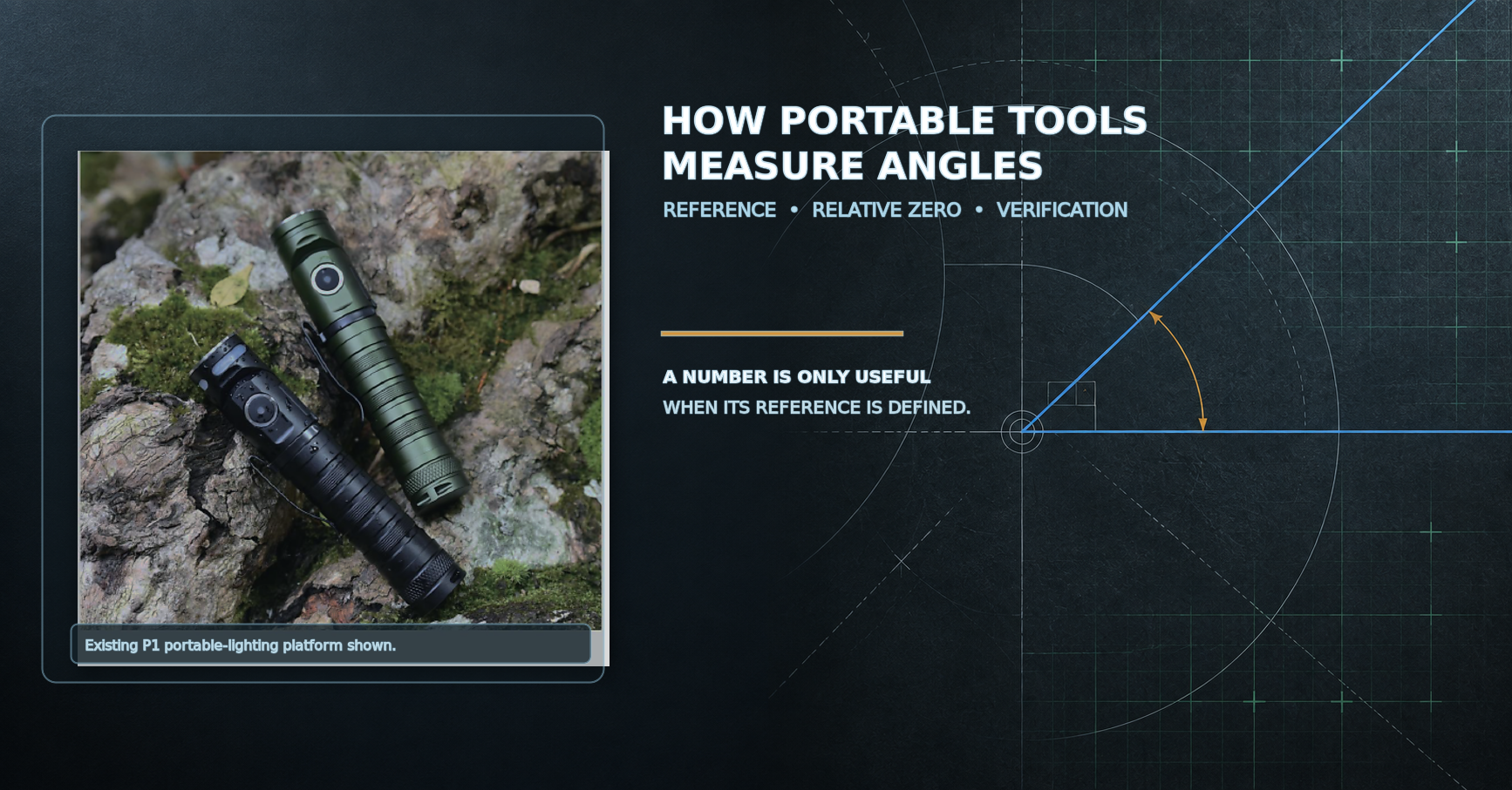

How does a portable electronic tool measure an angle?
A portable electronic tool measures angle by estimating its orientation relative to a defined reference—such as gravity or a user-set zero—and then relating the sensor orientation to the product's mechanical reference surface. The displayed value therefore comes from a chain, not from a sensor alone. A gravity-based task needs a defined gravity reference; a comparison task needs a clearly established starting orientation; and a surface-to-surface task needs controlled contact with both surfaces. If the relationship between sensor, housing, reference surface and zero logic is uncontrolled, a display can still show a stable number while systematically missing the angle the user actually needs. Buyers should first define the angle task, then the reference, datum, working conditions and evidence required for approval.
Every Angle Needs a Reference
Angle is not an isolated number. It is the rotational relationship of Orientation A to Reference B, or Surface A to Surface B. Before asking “Can it measure angle?”, the more useful buyer question is: “Relative to what?”
For absolute inclination relative to gravity.
The internal sensing axis used by the measurement system.
The controlled mechanical surface that connects the product to work.
A chosen relative reference for comparison.
Conceptual Angle-Measurement Chain
Absolute Angle and Relative Angle Answer Different Questions
| Measurement Type | Reference | User Question | Main Verification Need |
|---|---|---|---|
| Absolute Inclination | Gravity or defined absolute reference | How tilted is this orientation? | Known-reference and multi-position comparison |
| Relative Angle | User-set zero or first surface | How different is this from my chosen reference? | Reference transfer and repeat placement |
| Surface-to-Surface Angle | Surface A compared with Surface B | What is the angular relationship? | Datum, contact and workflow control |
If a user places the product on Surface A and sets zero, then moves it to Surface B, the reading can show the angle difference between B and A. Surface A does not need to be horizontal for that relative comparison to be useful. It simply cannot also be interpreted as an absolute gravity-based level reading.
Absolute angle measurement compares an orientation with a defined external reference, commonly gravity for inclination. Relative angle measurement compares a new orientation with a user-set or first-surface reference. The first answers how tilted something is relative to that external reference; the second answers how much one orientation differs from another. A relative-zero workflow can be highly useful even when the starting surface is already tilted. However, the resulting zero represents the chosen reference orientation, not an automatic claim that the product or workpiece is horizontal.
Gravity Can Provide an Absolute Reference—but the Sensor Axis Still Has to Be Controlled
Many electronic inclination systems use a gravity-sensitive sensing approach. In static or quasi-static conditions, acceleration components associated with gravity can be used to estimate orientation. This does not mean that an accelerometer directly measures angle: it senses acceleration components, and a measurement system estimates orientation from them. Motion, sustained vehicle acceleration, vibration or shock can add other acceleration components and change the measurement problem.
The sensor axis, PCB position and product orientation therefore need to be understood together. Different rotations—often described as pitch, roll or compound tilt—can create different requirements. When intended use allows compound tilt, validation should include multi-axis orientation rather than assuming that one simple rotation represents all use cases.
Additional sensing dimensions may support more complex orientation recognition, but accuracy still depends on sensor behavior, mechanical integration, calibration, algorithm choices, environment and verification.
The Product Datum Connects the Sensor Reading to the Real Workpiece
A buyer does not need the orientation of an internal component; the buyer needs the angle of a workpiece, fixture or reference surface. That requires a controlled relationship: sensor → PCB or mount → housing → measurement datum → workpiece. A visually flat industrial-design surface is not automatically a controlled measurement datum.
Bottom, side and back surfaces may be useful in handling or mounting, yet each intended measurement surface needs separate definition and verification. Curved surfaces, debris, fastener protrusions, uneven contact, soft materials, hand pressure and rocking can all change the product orientation at the moment of reading.
The reference surface is the mechanical bridge between an internal sensor reading and the real workpiece orientation. A sensor can behave consistently while the housing surface, mounting plane or contact condition introduces a different angle. The relevant relationship is sensor-to-housing-to-workpiece, not sensor alone. Buyers should identify the intended datum surface, how it contacts the workpiece and whether the same geometry is maintained across samples. If several surfaces may be used, each should be treated as its own measurement question rather than assumed equivalent.
Zeroing Turns One Orientation Into a Reference—If the Workflow Is Clearly Defined
Relative-angle work commonly follows a simple logic: place the product on Reference Surface A, set relative zero, move it to Surface B, read the difference, then repeat or verify. This is reference transfer. It is useful for comparing two orientations, transferring an existing angle or checking a fixture relationship.
Conceptual Relative-Angle Workflow
Moving from A to B can introduce a different contact surface, debris, unstable placement, changed datum selection or hand pressure. Zeroing defines the current reference. Calibration establishes or adjusts the relationship to a known reference. Verification checks whether the finished result meets the project requirement. These are related activities, but they are not interchangeable.
More Angular Digits Do Not Automatically Mean More Angular Accuracy
A display example such as 45.0° or 45.00° shows display resolution—the smallest increment presented to the user. It does not, by itself, establish system accuracy. Accuracy requires independent comparison with an appropriate known reference under defined conditions. Repeatability asks another question: whether the same setup, placed again, produces similar results.
A tool that displays increments of 0.1° is not automatically accurate to 0.1°. Resolution, accuracy and repeatability should be specified and verified separately.
No. A 0.1° display is only an illustrative resolution example: it describes the increment shown, not the closeness of the result to a known reference. Accuracy can be affected by sensor offset, sensor-axis alignment, PCB position, housing datum, zero logic, contact geometry, temperature and movement. A buyer should request an accuracy requirement separately, define the reference and intended working range, and use multi-point comparison to evaluate it. A stable display can still be consistently offset from the required angle.
Repeatability Shows Whether the Same Setup Produces Similar Angle Readings
Do not test repeatability by leaving a product untouched and repeatedly reading the same screen. A more meaningful review includes repositioning: place, read, remove, replace, read and compare. This exposes contact, seating and user-handling effects that a static screen check hides.
Agreement with reference and similar repeated results.
Consistent readings with a systematic offset.
Results change with placement or conditions.
Angle Measurement Changes When the Product Rotates Around Different Axes
A product may rotate in more than one direction. When it tilts simultaneously around different axes, some measurement architectures can experience cross-axis influence. Multi-axis orientation should therefore be included in validation when compound tilt is part of the intended use. The required review depends on the task; it should not be converted into an unsupported product-function promise.
| Condition | Measurement Challenge | Possible Design Response | Buyer Verification |
|---|---|---|---|
| Stable Workbench | Reference agreement | Defined datum and zero logic | Known-reference comparison |
| Handheld Movement | Changing contact and motion | Application-specific stability approach | Representative handling review |
| Machine Vibration | Reading variation | Filtering or timing logic if applicable | Use-condition evaluation |
| Compound Tilt | Cross-axis behavior | Architecture and algorithm review | Multi-axis orientation checks |
An Angle Reading Is Only as Reliable as the Physical Contact Used to Take It
Mechanical contact is part of the measurement system. A product can rock on a curved surface, sit unevenly on dirt, shift under hand pressure or contact a fastener instead of its intended datum. Magnetic seating, where applicable, also needs use-case review rather than assumption. Buyers should define whether the workpiece is flat, edged, tubular, curved or otherwise irregular before treating angle measurement as a suitable function.
Angle Measurement Is Usually a Static or Quasi-Static Task Unless the System Is Designed Otherwise
Hand movement, machine vibration and changing acceleration can cause reading variation. Dynamic measurement is a different engineering problem and should not be assumed from a static angle feature. Faster response can make a display react sooner; filtering or averaging may make a number appear more stable but can introduce response delay. Neither direction is universally best without a defined application.
Temperature Can Shift Both Sensor Behavior and Mechanical Alignment
Temperature can influence sensor offset, electronics, PCB position, housing geometry and the measurement datum. A project may need compensation, environmental verification or both, depending on its required use conditions. Buyers should define the relevant environment instead of assuming that a room-temperature result represents every operating condition.
A Drop Can Leave the Light Working but Change the Angle-Measurement Reference
Lighting Function Pass does not equal Measurement Function Pass. Impact can change the relationship among sensor mount, PCB, housing and datum without necessarily stopping the lighting function. Post-impact angle reverification is therefore an independent decision.
| Verification Item | Before Impact | After Impact | What to Compare |
|---|---|---|---|
| Zero | Record reference behavior | Repeat zero check | Change in reference result |
| Absolute Reference | Compare to known reference | Compare again | Indication relationship |
| Relative Angle | Transfer check | Repeat transfer check | Difference consistency |
| Repeatability | Repositioning review | Repositioning review | Placement variation |
| Product Datum | Inspect contact geometry | Inspect again | Damage or deformation |
| General Lighting Function | Function check | Function check | Separate lighting status |
How Should Buyers Verify a Portable Angle-Measurement Function?
Verification should begin with an appropriate reference for the required accuracy, not another unknown-error product. Review zero, known-reference agreement, multiple representative positions, repeated placement, relative-angle transfer, reversal-style checks where applicable, multi-axis orientation where relevant, pre/post-impact behavior, several samples and production-representative units. Verification points should represent the intended working range and product requirements; checking only one or two convenient orientations cannot prove the full measurement range.
Conceptual Verification Flow
Single-point agreement can hide scale, alignment or geometry errors elsewhere.
Relative difference can be useful while an absolute gravity reference still has offset.
Buyers should test the intended reference, zero logic, product datum, accuracy requirement, repeatability and multi-point behavior rather than relying on a single reading. Reviews should include real mounting or contact conditions, relative-angle transfer when relevant, compound orientation where relevant, movement or vibration exposure for the intended application, temperature direction, pre/post-impact comparison and production consistency. The evidence should identify the reference used, conditions, result, acceptance requirement and sample status. A finished unit should be verified separately from any calibration or adjustment process used during production.
Portable Angle Measurement Error Source Matrix
| Error Source | Possible Effect | How to Check | Control Direction |
|---|---|---|---|
| Sensor Offset | Systematic shift | Known reference | Calibration planning |
| Sensor-Axis Alignment | Orientation mismatch | Alignment review | Mount control |
| PCB Position | Datum shift | Assembly comparison | PCB locating features |
| Housing Datum | Workpiece mismatch | Datum inspection | Mechanical control |
| Contact-Surface Geometry | Rocking or tilt | Placement review | Define application surface |
| Surface Debris | False seating | Clean/repeat check | User procedure |
| Zero-Reference Error | Wrong starting point | Zero check | Clear logic |
| Relative-Zero Misuse | Wrong interpretation | Workflow review | User guidance |
| Cross-Axis Influence | Compound-tilt variation | Multi-axis review | Architecture validation |
| User Pressure | Changed orientation | Handling comparison | Contact design |
| Movement / Vibration | Reading variation | Representative use | Application definition |
| Temperature | Offset or geometry shift | Environmental review | Requirement control |
| Impact / Drop | Alignment change | Pre/post comparison | Reverification |
| Firmware / Filtering if applicable | Response trade-off | Behavior review | Change control |
| Sample-to-Sample Variation | Inconsistent units | Sample comparison | Process control |
| Production Calibration | Batch variation | Records and verification | Controlled process |
Portable Angle-Measurement Validation Matrix for B2B Buyers
| Validation Area | Buyer Question | Test Approach | Evidence | Risk if Unclear |
|---|---|---|---|---|
| Target Angle Task | What must be measured? | Write task before sampling | Approved brief | Wrong function |
| Absolute / Relative Requirement | Which result is needed? | Review both workflows | Use-case logic | Wrong interpretation |
| Gravity Reference | Is absolute inclination required? | Known-reference check | Comparison record | False absolute claim |
| Sensor Architecture | What engineering behavior is needed? | Feasibility review | Engineering decision | Unsupported requirement |
| Sensor Axis | Which orientation matters? | Axis review | Alignment evidence | Axis mismatch |
| Product Datum | Which surface contacts work? | Datum inspection | Drawing or sample review | Geometry error |
| Zero Logic | What does zero represent? | Zero-point review | Workflow record | User confusion |
| Relative-Zero Logic | Can it transfer a reference? | Surface A/B test | Difference result | Transfer error |
| Measurement Range | What orientations are required? | Representative points | Validation plan | Untested use area |
| Resolution | What increment is needed? | Display review | Requirement statement | Misleading digits |
| Accuracy | How close to reference? | Independent comparison | Result record | Unfit product |
| Repeatability | Will re-placement agree? | Remove and replace | Reading series | Unstable use |
| Multi-Axis Behavior | Does compound tilt occur? | Orientation review | Test notes | Unexpected variation |
| Mounting Stability | Does contact remain stable? | Use-surface review | Placement observations | False readings |
| Temperature Influence | What environment applies? | Project-specific review | Condition record | Field mismatch |
| Post-Impact Verification | Does reference change after impact? | Pre/post comparison | Reverification record | Hidden damage |
| Production Calibration | How is relationship established? | Process review | Control plan | Batch drift |
| Batch Consistency | Do units behave similarly? | Multiple-sample review | Comparison record | Launch variation |
Angle Measurement Terms at a Glance
| Term | Reference | What It Answers | Main Validation Question |
|---|---|---|---|
| Absolute Inclination | Gravity / absolute reference | How tilted is it? | Does it agree with a known reference? |
| Relative Angle | User zero / Surface A | How different is Surface B? | Does transfer remain consistent? |
| User Zero | Current chosen orientation | What becomes the baseline? | Is logic clear to the user? |
| Resolution | Display increment | What can be shown? | Is it confused with accuracy? |
| Accuracy | Known reference | How close is the result? | Has it been independently compared? |
Level vs Absolute Angle vs Relative Angle
| Function | Main Question | Reference | Typical Validation Focus |
|---|---|---|---|
| Level | Is the surface in a special gravity-related orientation? | Gravity | Level-reference behavior |
| Absolute Angle / Inclination | What quantified angle is present? | Gravity or defined absolute reference | Multi-point reference comparison |
| Relative Angle | How much did orientation change? | User-set zero / first surface | Transfer and repeat placement |
Buyer Quick Checklist
Five Mistakes Buyers Make When Evaluating Angle-Measuring Portable Tools
An angle request is incomplete without saying whether the task is gravity-based, relative or surface-to-surface. The same display can serve different workflows. The intended reference should be agreed before technical selection. Otherwise, sample feedback can conflict because users are judging different tasks.
More displayed digits may look reassuring, but they do not prove closeness to a reference. Accuracy needs independent verification. Repeatability needs re-placement checks. Both should be linked to the actual application requirement.
A relative zero records the starting orientation. If the start surface is tilted, later readings can still correctly show differences from it. They do not automatically describe gravity-based horizontal or vertical status. The UI and user workflow must make this distinction clear.
One successful comparison can conceal errors at other orientations. Verification points should represent the intended range and use geometry. They should also include relevant datums and placement conditions. A convenient check is useful, but it is not complete evidence.
An engineering sample can receive careful individual adjustment. Production requires a repeatable process for parts, assembly, calibration where required, verification and records. Finished-unit verification is not identical to calibration. Batch consistency must be defined before approval, not after launch.
Reliable use needs a defined reference, mechanical datum, controlled sensor alignment, calibration planning, repeatability, verification and production consistency.
Sixteen Tests or Reviews Buyers Should Use for an Angle-Measuring Portable-Light Prototype
How OEM/ODM Buyers Should Define an Angle-Measuring Portable Light Before Sampling
For portable-lighting projects that integrate angle measurement, the sensing system cannot be separated from the product datum, PCB position, housing structure, zero logic and production-verification process. SHENGQI can support these engineering stages within its OEM/ODM portable-lighting development process, including industrial design, electronic design, PCB layout, mechanical integration, optical engineering, manufacturing, testing and quality control.
A complete brief should define target market, target user, primary lighting task, angle-measurement task, absolute or relative requirement, reference method, product datum, measurement-range direction, accuracy requirement, resolution requirement, repeatability requirement, zeroing logic, multi-axis requirement where relevant, static or dynamic environment, mounting method, temperature environment, impact requirement, display or feedback requirement, calibration requirement, production-verification requirement, estimated quantity and target timeline.
“Need flashlight with angle measurement, very accurate.”
It does not define the reference, absolute or relative task, range, accuracy, resolution, mounting or verification method.
Application, angle task, reference, absolute/relative requirement, measurement range, accuracy, resolution, repeatability, zero logic, mounting method, calibration requirement, verification method and estimated quantity.
“Very accurate angle measurement” is not a complete engineering requirement. Translate broad requests into decisions: “Need angle measurement” becomes “Absolute inclination or relative angle?”; “Need 0.1 degree” becomes “Display resolution, accuracy requirement or both?”; “Need zero” becomes “Absolute zero, relative zero or calibration zero?”; and “Need stable number” becomes “What response expectation and movement environment apply?”
| Buyer Wants | Potential Engineering Trade-Off | Question to Resolve |
|---|---|---|
| Higher Resolution | Can create misleading confidence | What accuracy is required? |
| Higher Accuracy | More datum and process control | What reference and evidence apply? |
| Wider Angle Range | Different orientation behavior | Which range is actually used? |
| Faster Response | More visible reading variation | How dynamic is the task? |
| More Stable Reading | Possible response delay | What user response is acceptable? |
| More Axes | More validation complexity | Which orientations matter? |
| Smaller Product | Less room for datum and PCB control | What physical datum is needed? |
| Lower Weight | Potential mounting changes | How is stable contact maintained? |
| Higher Impact Resistance | More mechanical validation | What requires rechecking after impact? |
| Lower Cost | Reduced design or process margin | Which measurement requirements are essential? |
Buyers can position the angle-measurement concept alongside relevant portable task-lighting platforms and the broader portable lighting product range. Before approval, they should review available portable-light testing and quality-control capabilities and the applicable manufacturing process. A component change can become a measurement-system change even if the product looks identical: sensor, PCB, firmware, housing, datum component, mounting structure or calibration-method changes may require revalidation.
Conceptual Production Flow
Frequently Asked Questions About Angle Measurement in Portable Tools
1. What is the difference between absolute and relative angle measurement?
Absolute measurement compares an orientation with gravity or another defined external reference. Relative measurement compares a new orientation with a user-set zero or first surface. They answer different questions and need different workflows.
2. Does a higher display resolution mean better angle accuracy?
No. Resolution is the increment shown on the display. Accuracy is the closeness of a result to an appropriate reference and must be independently verified.
3. What does zero mean in a digital angle-measuring tool?
Zero can represent an absolute reference, a user-defined relative reference or part of a calibration process. The product workflow must make the intended meaning clear.
4. Can a relative-zero function be used to transfer an angle between two surfaces?
Yes, depending on the product's intended reference-transfer logic and validation. Surface A becomes the relative baseline, and the reading on Surface B represents the difference, provided contact and datum conditions are controlled.
5. Why does the product reference surface affect the angle reading?
It connects the sensor orientation to the real workpiece. If the datum geometry, contact surface or housing relationship shifts, the displayed value may not represent the intended workpiece angle.
6. Why should angle measurement be tested at multiple positions instead of one angle?
One point can hide alignment, scale, contact or geometry errors elsewhere. Multiple representative positions provide stronger evidence across the intended working range.
7. Can a drop affect angle measurement even when the lighting function still works?
Yes, it can. An impact may alter the sensor-to-PCB-to-housing relationship or damage the measurement datum while the lighting function still operates. Reverification should be considered separately.
8. Can angle-measurement functions be integrated into an OEM/ODM portable-lighting project?
Yes, subject to sensor architecture, mechanical datum, target accuracy, product platform, engineering feasibility and verification requirements. The feature must be developed as a controlled measurement system, not only as a display addition.
Reference and Verification Make an Angle Value Useful
A useful angle-measurement function is not defined by how many digits appear on the display. It is defined by whether the reference, product datum, sensor alignment, zero logic, repeatability and verification process remain controlled from prototype through production.
For buyers, the practical starting point is simple: define the angle task, identify what the number is relative to, define the physical datum and validate across the intended conditions. That creates a better basis for product development than asking for an angle feature in isolation.
Shengqi Lighting is evaluating a new Angle-Measuring Flashlight direction for its 140th Canton Fair new-product program. Visit Booth 16.4F25 from October 15–19, 2026 for an early preview. Final measurement functions, operating logic and specifications remain subject to engineering validation.
Developing a Portable Light With Integrated Angle Measurement?
For an OEM/ODM technical evaluation, prepare the target market, target user, primary lighting task, angle-measurement task, absolute or relative requirement, reference method, product datum, measurement range, accuracy, resolution, repeatability, zero or reference-transfer requirement, static or dynamic environment, mounting method, impact requirement, calibration requirement, production-verification requirement, estimated quantity and target timeline.
Contact SHENGQI LIGHTING through the contact page or at sales@shengqilight.com for an OEM/ODM technical evaluation.